Igneus V2 for the Anet ET4 — 4010 blowers and LED light
Remix of IGNEUS V2 - E3D V6/VOLCANO - ANET ET4 / ET4 PRO / ET4X / ET5 by Locos3D, licensed under CC BY-NC-SA 4.0, like the original.
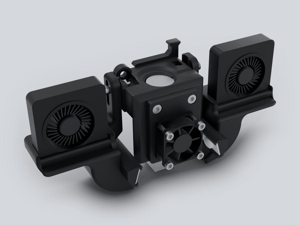
Built and running
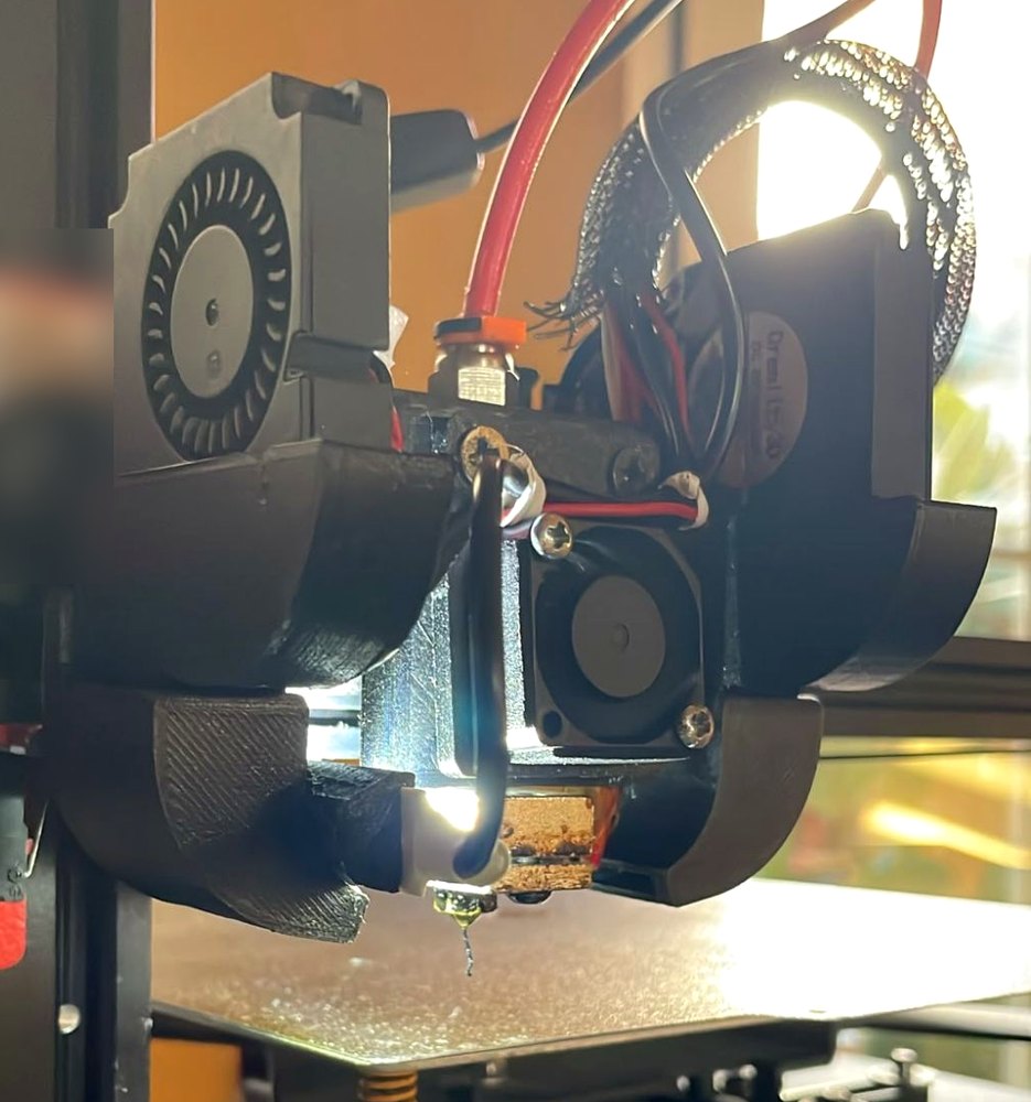
Printed and running on an Anet ET4: the 4010 blowers on the original ducts, the 2510 hotend fan on the front clamp and the LEDs lighting the nozzle.
What this remix adds
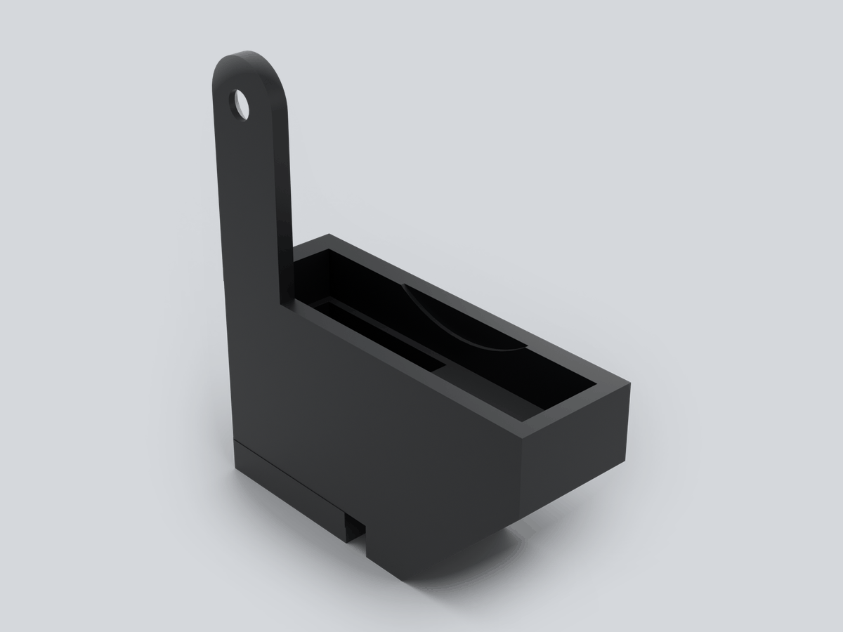
- 4010 adapter to fit the Ender 3's stock 4010 blowers to the original 5015 ducts, in two versions: normal (the blower standing in the original position, push-fitted in the cradle; the adapter plugs into the duct and is screwed to its ear) and flat (the blower on top with its intake facing the front, like the hotend fan; the adapter is only 15 mm tall, so the blowers sit low).
- LED mount that fits on the inside of each original duct, held with a zip tie, and aims two LEDs of a 24 V LED strip with one lensed LED per segment, like the light strips sold for the Bambu Lab A1, at the nozzle.
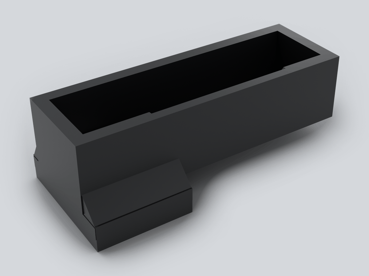
- One-piece duct, in both versions, if you prefer to reprint the ducts: duct, fan cradle, mounting arm and LED channel drawn as a single part with rounded, flowing lines, not the adapter stuck onto the original duct. It keeps the original's rails, height slot and air channel, so it mounts and aims the air the same way.
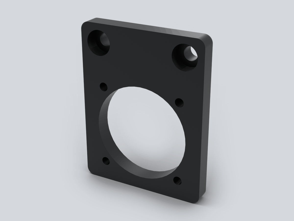
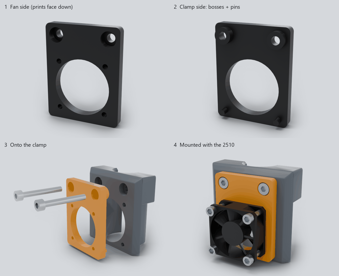
- 25 → 30 mm fan adapter so the 2510 hotend fan of an Anycubic Kobra X fits Locos3D's 30 mm fan clamp.
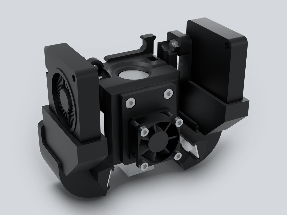
Normal
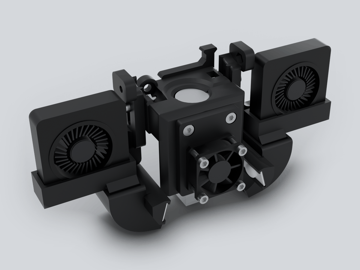
Flat
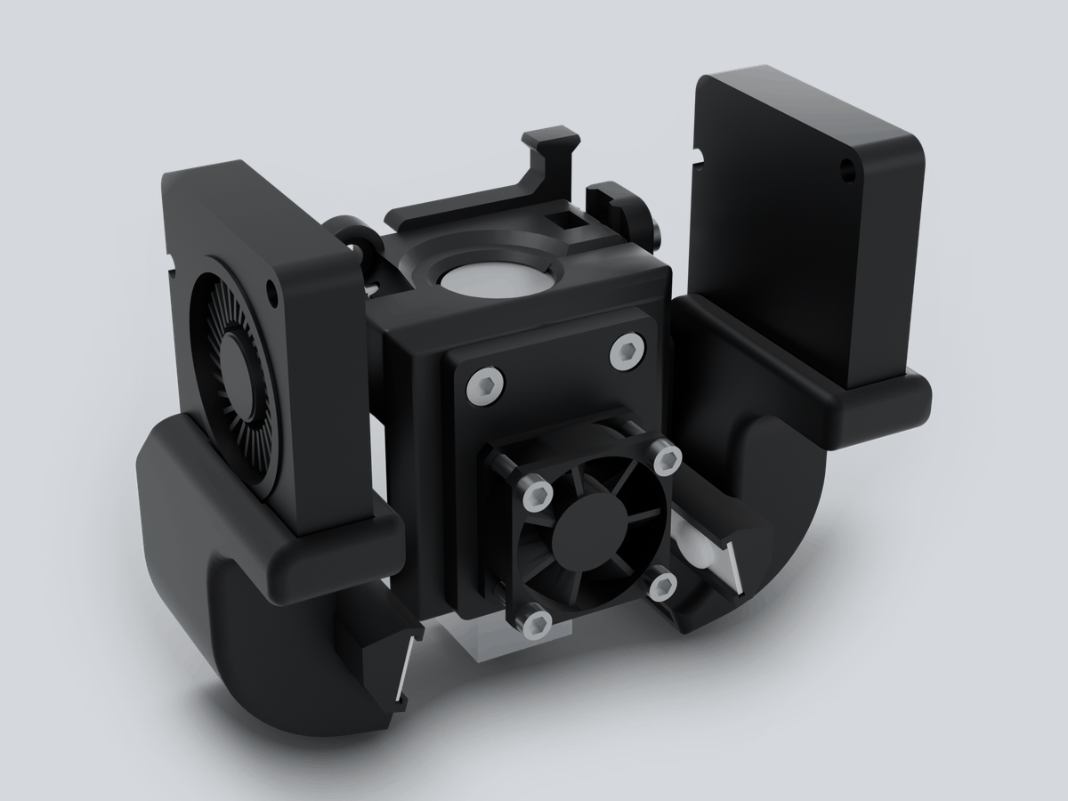
One-piece, normal
One-piece, flat
Rendered in Blender from the CAD models.
Downloads
All files are oriented for printing and none of them needs supports: every overhang is 45° or steeper and the few flat ceilings left are short bridges between two walls. Right and left parts are mirror images. To enter your own measurements (fan, LED strip, clearances) use the part generator.
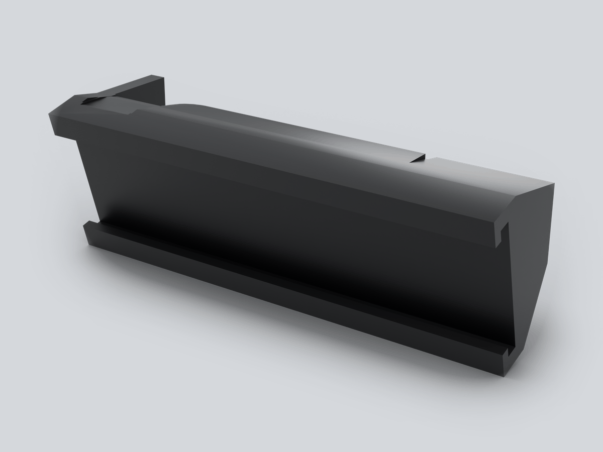
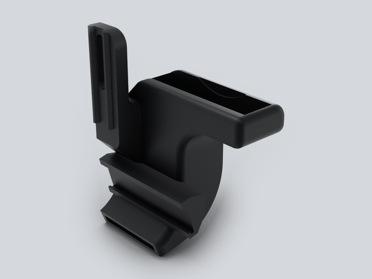
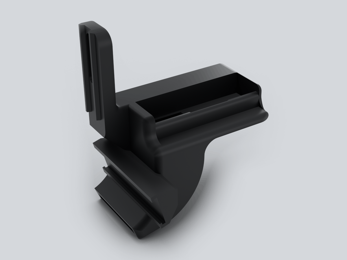
One-piece duct with LED channel, flat
On its flat back face, no supports (the low front wall of the cradle prints as a bridge).
Printing
- Material: PETG, ASA or ABS. The ducts and adapters end a few millimetres from the heater block and the hot nozzle: PLA softens there and the ducts sag.
- Settings that suit these parts: 0.4 mm nozzle, 0.2 mm layers, 3–4 walls, 20–40 % infill. The duct walls are 1.5–3 mm thick, so with 3–4 walls they print solid.
- No supports, in the orientation of the files.
- Brim on the two tall, narrow parts: the normal 4010 adapter (51 mm tall, standing on its nozzle) and the LED mount (39 mm tall on a 12 × 13 mm footprint).
Hardware
Per side (right and left), depending on the version you build:
| Part | Hardware |
|---|---|
| Every version | 4010 blower, 24 V (the Ender 3's stock part-cooling fan) |
| Original or one-piece duct | M3 × 14 socket head screw and M3 nut, through the height slot into the body's nut pocket |
| 4010 adapter, normal | M3 × 10 countersunk screw and M3 nut, through the adapter's arm and the duct's ear. The blower is push-fitted in the cradle, no screws |
| 4010 adapter, flat | None: the cradle holds the blower |
| LED mount | A small zip tie, up to 3.2 mm wide and 1.4 mm thick |
| LEDs | 2 LEDs of a 24 V strip with one lensed LED per segment (10 mm wide, cut marks 18.1 mm apart) |
For the 2510 fan adapter (one, on the front clamp): the clamp's two M3 screws, about 4 mm longer than without it (M3 × 24 in place of M3 × 20), and 4 self-tapping M2.5 × 12 screws for the fan.
Assembly notes
- Blowers: wire both 4010 blowers in parallel to the printer's part-cooling fan output, so they always run at the same speed.
- LEDs: on this kind of strip each LED is its own segment. Cut it at the marks, two LEDs per side, and wire both pieces in parallel to 24 V.
- 2510 fan adapter: it is held by the clamp's own two M3 screws, and the fan is fixed to it with the 4 self-tapping M2.5 screws.
Original parts
Everything else is Locos3D's original Igneus V2: download it from Thingiverse (assembly guide). This build uses:
| File | Qty | What it is |
|---|---|---|
Igneus_Version1_Rev.3.stl | 1 | Body for the E3D V6 |
Abrazadera_Adapter_Fan_30mm.stl | 1 | Front clamp with the 30 mm fan mount |
Tobera_5015_V2.stl | 2 | 5015 duct, one of them mirrored for the left side (not needed with the one-piece ducts) |